
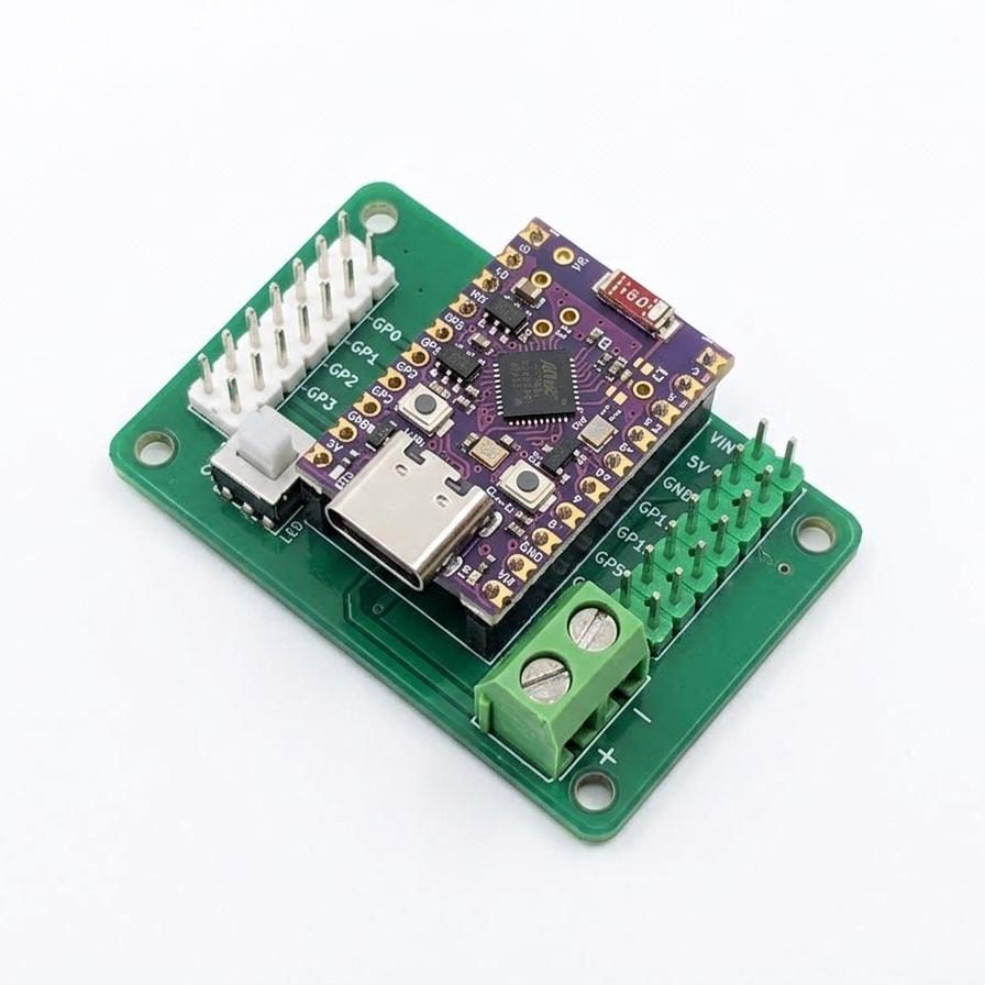
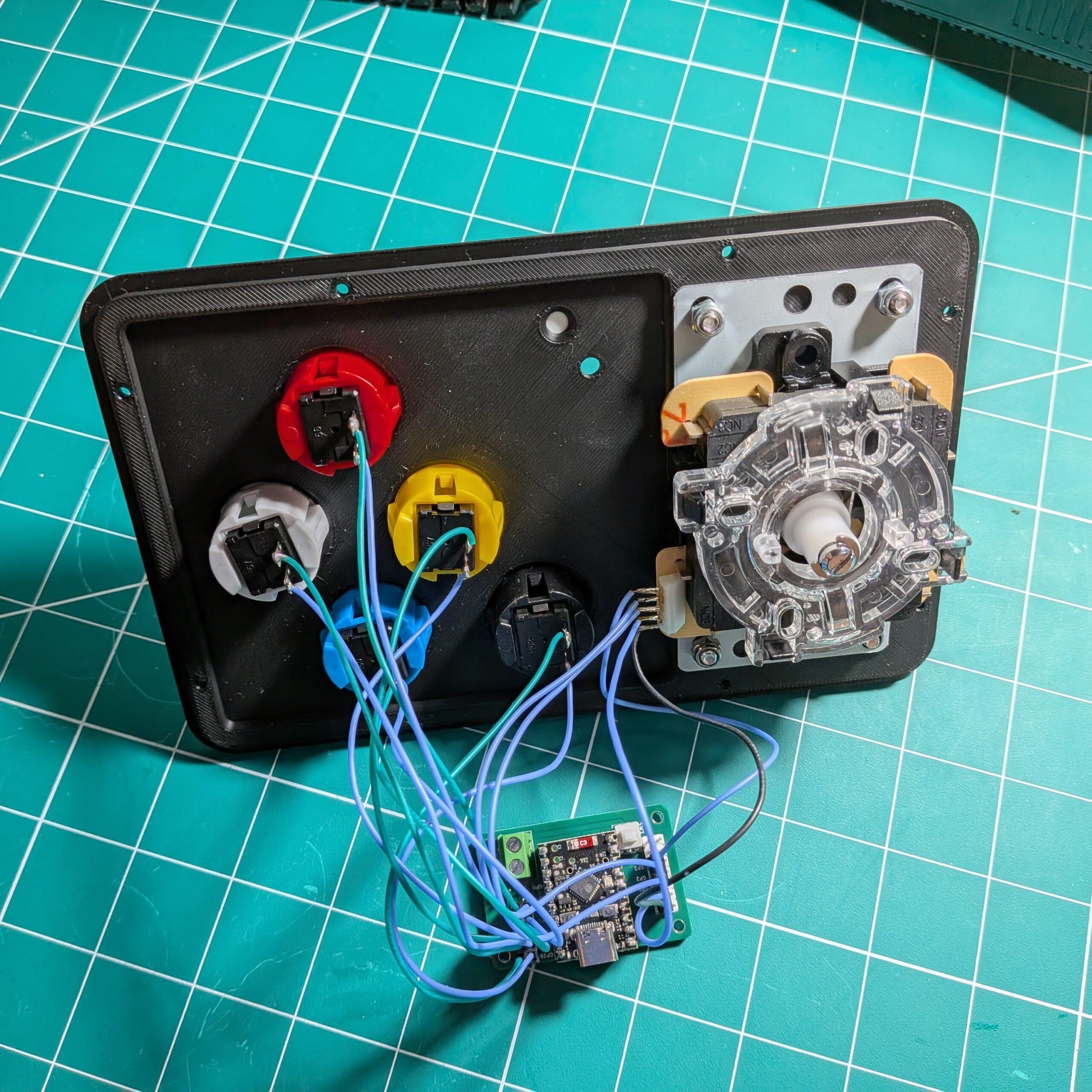
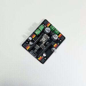
The Arcade Controller Board is the custom ESP32-C6 carrier PCB behind the RookiDroid Arcade Controller. Joystick header, button header, battery terminal, power switch and the 9 V step-down are all on one board, so a real arcade joystick and five microswitch buttons become a WiFi robot remote without a breadboard or a single soldered joint. Plug in the joystick harness, run one wire per button, flash the open-source sketch, and your hexapod answers to the stick.
Arcade Hardware, Straight In
Arcade parts are plain switches — but nine of them, a battery and a microcontroller usually means a nest of wiring. This board is laid out so that wiring is trivial and hard to get wrong.
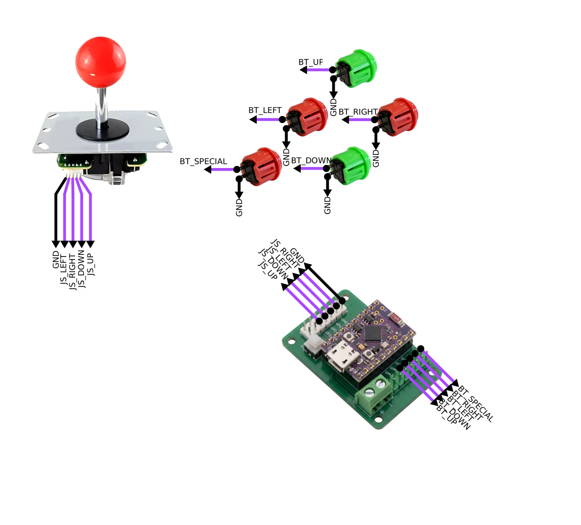
- Dedicated joystick header: a 5-pin connector takes the joystick’s stock harness — all four directions and their common ground in one plug, no crimping.
- Labelled button header: a 2×7 header carries the five button GPIOs plus ground, 5 V and VIN pins, so each button is one wire to its signal pin and one to any ground.
- Internal pull-ups, no debounce circuitry: every input is just a switch to ground. The firmware handles the rest, and the command is re-sent every 50 ms anyway.
- On-board power: a 2-pin screw terminal takes a 9 V battery snap connector, an on-board buck converter turns it into a clean 5 V rail, and a slide switch cuts it all.
Key Specs
- Microcontroller: ESP32-C6 SuperMini — 2.4 GHz WiFi, USB-C for flashing
- Joystick header: 5-pin, mapped to
GP0–GP3plus ground - Button header: 2×7, with the five button inputs on
GP14,GP15,GP18,GP19andGP20, alongside GND, 5 V and VIN pins - Power input: 2-pin screw terminal for a 9 V battery, with a Mini360 buck converter to 5 V and a slide power switch on the board
- Status LED: the SuperMini’s WS2812 RGB LED on
GP8— green when connected, red when the link drops - Control: 6-byte binary UDP packets to the robot’s access point at
192.168.4.1:1234, sent at 20 Hz - Compatibility: drives Hexapod Nougat, Mochi and Macaroon — they share one protocol
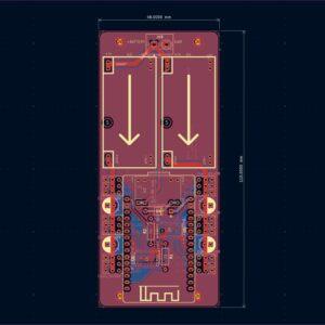
- Mounting: M2 screw holes matching the printed arcade body
- Firmware: open-source Arduino sketch, MIT licensed
What’s Included
- 1 × Arcade Controller Board — buck converter, power switch, screw terminal and both headers already assembled and tested
- Not included: the arcade joystick, the five push buttons, the 9 V battery and its connector, and the printed cabinet — the cabinet is a free download
Why This Board
- No soldering: headers, terminal and power section are assembled. Plug the joystick in and push spade connectors onto the button wires.
- One battery, no regulator to source: a single 9 V cell runs the whole remote, stepped down on-board.
- Fits the printed cabinet: mounting holes and connector positions line up with the arcade body, with the USB-C port left reachable for flashing.
- Wireless from day one: the remote joins the robot’s own access point — no router, no pairing, no app.
- One remote, three robots: point the sketch at Nougat, Mochi or Macaroon by changing a single line.
- Open hardware: the wiring diagram, pin map and firmware are all public on GitHub.
Getting Started
- Print the cabinet from the free 3D print files and mount the board in the body with four M2×4mm screws.
- Plug the joystick harness into the 5-pin header, then run one wire from each button to its GPIO on the 2×7 header and one to any
GNDpin. - Screw the 9 V snap connector into the terminal block, minding polarity.
- Install Arduino IDE 2.x, add the esp32 board package (3.x or newer) and the Adafruit NeoPixel library.
- Open
arcade.ino, setssidto your robot’s network, select ESP32C6 Dev Module, and upload over USB-C. - Power the robot up first, then the remote. The LED turns green when the link is live — push the stick and it walks.
Safety: check the 9 V polarity twice before the first power-up. The screw terminal will happily accept reversed leads, and that can destroy the buck converter and the ESP32-C6.
Open hardware, open firmware. Plug it in and take the controls.
Reviews
There are no reviews yet.