Open-source robot remote
Build the Arcade Remote
A real arcade joystick, five snap-in buttons and an ESP32-C6 in a 3D-printed cabinet — a WiFi controller for every RookiDroid hexapod, in four phases from printing to your first walk command.
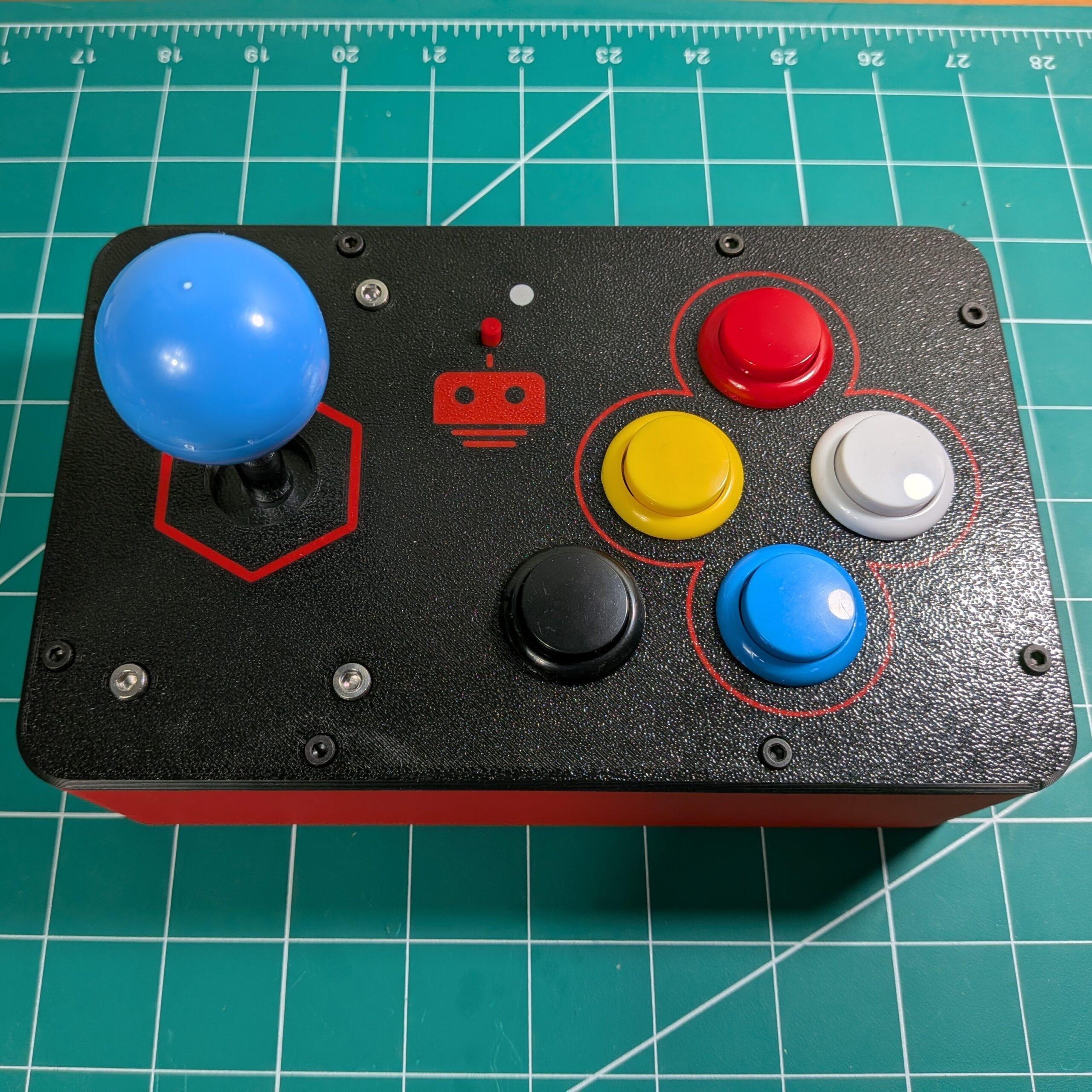
What you’ll build
Inputs9 switches — joystick + 5 buttons
Build time2–3 hours after printing
Skill levelBeginner
ToolsHex key set, small screwdriver


Works with all three hexapods. The same remote drives Nougat ↗, Mochi ↗ and Macaroon ↗ — they all speak the same binary UDP protocol. Point the firmware at the robot’s access point and you’re done; see Phase 03.
No soldering required with the arcade controller board ↗ — the joystick harness plugs into its 5-pin header and the button wires push onto the 2×7 header. A bare ESP32-C6 SuperMini works too, if you wire the nine switches straight to the GPIOs in the pin map and feed it 5 V.
Specifications
| Controller | ESP32-C6 SuperMini on the RookiDroid remote carrier board |
| Inputs | 4-way microswitch joystick + 5 arcade push buttons — all digital, no analog stick and no deadzone |
| Feedback | 1 × WS2812 (NeoPixel) RGB status LED on GP8, visible through the window in the top panel |
| Power | 9 V battery → on-board Mini360 buck converter → 5 V, with a slide switch on the board |
| Connectivity | 2.4 GHz WiFi — the remote joins the robot’s own access point as a station, so no router is involved |
| Control | 6-byte binary UDP packets to 192.168.4.1:1234 |
| Update rate | 20 Hz (50 ms loop), sent continuously including standby |
| Enclosure | 3D-printed body, cover, bottom plate and magnetically-latched battery cover |
Safety notes
- Check the 9 V polarity twice before the first power-up — the snap connector screws into a plain terminal block, and reversed leads can destroy the buck converter and the ESP32-C6
- Power the robot up first, then the remote. The firmware waits for the robot’s access point before it does anything else
- Give the robot room before you test. The remote starts sending commands the moment the LED turns green
- Keep the small magnets clear of the battery leads while you press them in — they will happily jump to anything ferrous nearby
Print settings
Layer height0.2 mm
Nozzle0.4 mm
MaterialPLA
Printer profileBambu Lab H2S
The whole cabinet is one Bambu Studio project —
arcade.3mf is a free download ↗, and the Fusion 360 source is arcade.f3d ↗ on GitHub. The cover is multi-material so the logo and the button outlines print in a second color — print it in a single color if you don’t have an AMS.
Printed parts
| Part | Qty | Note |
|---|---|---|
| arcade body | 1 | Holds the controller board and the battery bay |
| arcade cover | 1 | Top panel with the joystick, button and LED cut-outs Multi-color |
| bottom | 1 | Closes the underside |
| battery cover | 1 | Magnetic latch — no screws |
Hardware
All standard metric parts — available from Amazon, AliExpress, or local hardware stores. Sort them into labeled containers before you start.
| Item | Spec | Qty | Use |
|---|---|---|---|
| Screw | M3 × 10 mm | 8 | Cover to body |
| Nut | M3 hex nut | 8 | Cover to body |
| Screw | M4 × 10 mm | 4 | Joystick mounting plate |
| Nut | M4 hex nut | 4 | Joystick mounting plate |
| Screw | M2 × 4 mm | 4 | Controller board to body |
| Magnet | 6 mm dia. × 2 mm | 4 | Hold the battery cover — half in the bay, half in the cover |
Assembly order
1
Clean up the cut-outs. The buttons and the joystick shaft need a snug snap fit — deburr the openings and test-fit one button before pressing all five home
2
Mount the inputs in the cover. Snap the five 30 mm buttons in, then bolt the joystick plate down with the M4 screws and nuts

3
Mount the controller board in the body with the four M2 × 4 mm screws, keeping the USB-C port reachable for flashing
4
Wire it up — joystick harness into the 5-pin header, one wire from each button terminal to the 2×7 header. Full details in Phase 02 — Electronics
5
Fit the battery hardware. Screw the 9 V snap connector leads into the terminal block — minding polarity — and press the magnets into the battery bay and its cover so the pairs attract rather than repel
6
Close it up with the eight M3 screws and nuts, fit the bottom plate, then flash the firmware and power it on
Flash and test the board before you screw the cover down — a swapped button wire is much easier to fix with the cabinet still open.
Components
| Image | Component | Spec | Qty | Note |
|---|---|---|---|---|
 | Controller board | ESP32-C6 SuperMini on a carrier board — Mini360 buck converter, power switch, 2-pin battery terminal, 5-pin joystick header and a 2×7 button header | 1 | Purchase ↗ — or use a bare ESP32-C6 SuperMini and wire the switches straight to the GPIOs below |
 | Arcade joystick | Microswitch joystick, 97 × 65 mm mounting plate, ~119 mm overall height, 5-pin harness | 1 | Ball top; the harness plugs into the joystick header |
 | Arcade push button | 30 mm snap-in button with a 2-terminal microswitch | 5 | Any five colors — four for the direction cluster, one for the special button |
 | 9 V battery connector | Snap connector with flying leads | 1 | Screws into the 2-pin terminal block Mind polarity |
 | 9 V battery | Alkaline or rechargeable | 1 | Sits in the bay behind the magnetic cover |
| Jumper wires | 2.8 mm spade or Dupont, 150–200 mm | ~11 | One per button terminal — the joystick comes with its own harness |
Connection diagram

Every input is a plain switch to ground. The firmware enables the internal pull-ups (
INPUT_PULLUP), so one terminal of each microswitch goes to its signal pin and the other to any GND pin — no 5 V wire runs to a button, and there is no debounce logic, because the command is re-sent every 50 ms anyway.
Pin map
| Input | Signal | GPIO | Where it lands on the board |
|---|---|---|---|
| Joystick up | JS_UP | GP3 | 5-pin joystick header |
| Joystick down | JS_DOWN | GP2 | 5-pin joystick header |
| Joystick left | JS_LEFT | GP0 | 5-pin joystick header |
| Joystick right | JS_RIGHT | GP1 | 5-pin joystick header |
| Button — up | BT_UP | GP14 | 2×7 button header |
| Button — down | BT_DOWN | GP15 | 2×7 button header |
| Button — left | BT_LEFT | GP18 | 2×7 button header |
| Button — right | BT_RIGHT | GP19 | 2×7 button header |
| Button — special | BT_SPECIAL | GP20 | 2×7 button header |
| Status LED | PIN_RGB | GP8 | On-board WS2812 of the SuperMini |
The four direction buttons are the cluster outlined on the top panel; the button sitting on its own is the special (modifier) button.
Wiring
1
Plug the joystick harness into the 5-pin header — that covers all four directions and their ground in one connector
2
Run one wire from each button’s signal terminal to its GPIO on the 2×7 header, following the pin map above
3
Run the second terminal of each button to any
GND pin — daisy-chaining the grounds is fine4
Screw the 9 V connector leads into the 2-pin terminal block, red to +, black to −, and leave the slide switch off until you have double-checked it
5
Dress the wires so nothing is pinched between the cover and the body when you close the cabinet
Prerequisites
| Requirement | How to install |
|---|---|
| Arduino IDE 2.x | Download from arduino.cc ↗ |
esp32 board package | Version 3.x or newer (Espressif Systems) — required for ESP32-C6 support. Boards Manager → search esp32 |
Adafruit NeoPixel | Arduino IDE → Library Manager → search and install |
WiFi, WiFiUdp | Included with the esp32 board package — nothing extra to install |
Upload steps
1
Download the firmware and open
software/arcade/arcade.ino ↗2
Select board
ESP32C6 Dev Module, and the port that appears when you plug in the USB-C cable3
Check the WiFi settings near the top of the sketch match your robot — see the configuration below
4
Upload. If the port never enumerates, hold BOOT, tap RESET, release BOOT, and try again
5
Open the Serial Monitor at 115200 baud to watch the WiFi connection — it prints a dot every 500 ms until the robot’s access point answers, then the IP address it was given
Default configuration
As the sketch ships — set up for a Nougat. The table below has the values for the other hexapods.
ssid
hexapod_nougat
password
hexapod_1234
udpAddress
192.168.4.1
udpPort
1234
setup() blocks until the robot’s network is reachable, so power the robot up first. Until the remote connects it does nothing and the LED stays off — that is normal, not a fault.
Which hexapod are you driving?
The remote works with all three hexapods — only the
ssid line changes. Every robot hosts its own access point at 192.168.4.1 and listens on port 1234, so password, udpAddress and udpPort stay as they ship.
| Robot | Set ssid to | Password | Build guide |
|---|---|---|---|
| Hexapod Nougat | hexapod_nougat | hexapod_1234 | Build Nougat ↗ |
| Hexapod Mochi | hexapod | hexapod_1234 | Build Mochi ↗ |
| Hexapod Macaroon | hexapod_macaroon | hexapod_1234 | Build Macaroon ↗ |
Changed your robot’s credentials in its own
config.h? Match them here. Driving something else entirely works too — any robot that accepts the 6-byte packet on a known IP and port can be flown from this remote.
Status LED
| Color | Meaning |
|---|---|
| Off | Still connecting — or no power |
| Green | Connected — commands are being sent |
| Red | WiFi lost. The sketch keeps running and recovers by itself when the robot comes back |
How the sketch works
1
setup() puts all nine switch pins in INPUT_PULLUP, starts the NeoPixel, then blocks in connectToWiFi() until the robot’s AP accepts it2
A WiFi event handler opens the UDP socket and turns the LED green on
GOT_IP, or red on disconnect3
loop() reads all nine pins, resolves exactly one command from them, sends it as a 6-byte packet, and waits 50 ms — a 20 Hz heartbeat4
Nothing pressed resolves to
CMD_STANDBY, which is why the robot stops the instant you let go — there is no separate stop buttonTroubleshooting the upload
- Board doesn’t enumerate over USB: hold BOOT, tap RESET, release BOOT, then upload
- No
ESP32C6 Dev Modulein the board list: the esp32 board package is older than 3.x — update it in Boards Manager - Compile fails on
Adafruit_NeoPixel.h: the library isn’t installed, or the IDE is still pointed at a non-ESP32 board - Nothing on the Serial Monitor: check the baud rate is 115200, and that the cable carries data rather than power only
Every 50 ms the firmware reads all nine switches and sends exactly one command. The joystick takes priority over the buttons, and nothing pressed sends
CMD_STANDBY.
Control map
Joystick — walking
Upwalk forward
Downwalk backward
Leftsidestep left
Rightsidestep right
Up + Leftforward-left
Up + Rightforward-right
Down + Leftbackward-left
Down + Rightbackward-right
Buttons — joystick centered
Upwalk forward
Downwalk backward
Leftturn left
Rightturn right
Special + Upbody pitch
Special + Leftbody roll
Special + Rightbody yaw
Special + Downbody twist
Turbo. Hold the up button while pushing the joystick up for
CMD_FAST_FORWARD, or the down button while pulling the joystick down for CMD_FAST_BACKWARD.
Commands sent
| ID | Command | Control |
|---|---|---|
0 | CMD_STANDBY | Nothing pressed |
1 | CMD_WALK_0 | Joystick up, or the up button |
2 | CMD_WALK_180 | Joystick down, or the down button |
3 | CMD_WALK_R45 | Joystick up + right |
4 | CMD_WALK_R90 | Joystick right |
5 | CMD_WALK_R135 | Joystick down + right |
6 | CMD_WALK_L45 | Joystick up + left |
7 | CMD_WALK_L90 | Joystick left |
8 | CMD_WALK_L135 | Joystick down + left |
9 | CMD_FAST_FORWARD | Joystick up + up button Turbo |
10 | CMD_FAST_BACKWARD | Joystick down + down button Turbo |
11 | CMD_TURN_LEFT | Left button |
12 | CMD_TURN_RIGHT | Right button |
13 | CMD_CLIMB_FORWARD | Not mapped to a control |
14 | CMD_CLIMB_BACKWARD | Not mapped to a control |
15 | CMD_ROTATE_X | Special + up — body pitch |
16 | CMD_ROTATE_Y | Special + left — body roll |
17 | CMD_ROTATE_Z | Special + right — body yaw |
18 | CMD_TWIST | Special + down — body twist |
UDP protocol
Each packet is 6 bytes, little-endian and unpadded, sent to
192.168.4.1:1234. The layout matches UdpControlPacket in the hexapod firmware — see the UDP command reference ↗ for the other packet types the robot understands.
| Offset | Field | Type | Value |
|---|---|---|---|
0 | magic | uint8 | 0xA5 — motion command |
1 | cmd | uint8 | Command ID from the table above |
2–5 | seq_num | uint32 | Increments on every packet |
First test
1
Power the robot up first and give it clear space — it starts moving as soon as a command arrives
2
Slide the remote’s power switch on. The LED stays off while it hunts for the access point, then turns green
3
Nudge the joystick up — the robot should walk forward, and stop the moment you release it
4
Work around every input once: four joystick directions, four diagonals, four direction buttons, and the four special combinations
5
Happy with it? Close the cabinet with the M3 hardware and drop the 9 V battery in behind the magnetic cover
Troubleshooting
| Symptom | Things to check |
|---|---|
| LED stays off, Serial prints dots forever | The robot isn’t powered up, or the SSID/password don’t match — setup() waits for the AP |
| LED is green but the robot ignores the remote | udpAddress and udpPort must match the robot, and the robot must be in its normal (non-calibration) mode |
| One direction never triggers | Check that switch’s signal wire and its GND — an unconnected INPUT_PULLUP pin just reads high forever |
| Diagonals don’t work | The joystick has a 4-way restrictor plate fitted — swap in the 8-way gate |
| Robot keeps moving after you let go | Standby packets aren’t arriving — check the WiFi link; the robot should also have its own failsafe |
| The wrong action fires | Only one command is sent per cycle and the joystick wins — if a button acts like a joystick direction, check it isn’t wired to a joystick GPIO |
| Board doesn’t enumerate over USB | Hold BOOT, tap RESET, release BOOT, then upload |
Full sources, print files and issue tracker: github.com/rookidroid/remote-arcade ↗ — MIT licensed, and build questions are welcome in Issues.